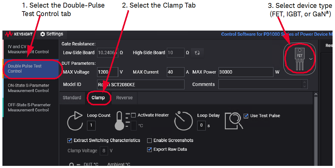
Run the Clamp Double-Pulse Test
The DPT Clamp Test is the same as the Standard test but uses the Clamp Circuit on the GaN Test Module. For accurate RDS(on) measurements the clamping circuit limits the applied voltage level to the oscilloscope probe while the DUT is turned off. This way an oscilloscope probe with a lower divider ratio (10:1) can be used for accurately measuring VDS while the transistor is turned on.
Use these Double-Pulse Test Modules and Oscilloscope Probes
This Clamped DPT test uses the following Test Modules and Oscilloscope Probes:
- 10076C 100:1 High Voltage Probe for measuring VDS on the DUT Module
- PD1000-60002 Protection Probe for measuring ID.
- N2873 10:1 Standard Oscilloscope Probe for measuring VGS on the Low-Side Gate Drive Module.
- N2873 10:1 Standard Oscilloscope Probe for measuring VDS on the Clamp Circuit Module.
The Clamp Circuit provides the following:
- Clamps voltage to levels suitable for using the N2873A 10:1 passive probe
- Characterized systematic errors so that they can be taken into account
- Quantified achievable accuracy
a. GaN devices require a special DUT Test Board and a software license. Contact Keysight for information.
Parameter Settings
After setting the test parameters, click the Start button to start the test.